Backstops are located on high speed shaft or first intermediate shaft of a reducer and as holdbacks on the head shaft of conveyors.
Backstops and overrunning clutches are used wherever you want or must provide for only one direction of rotation. They are usually installed between a shaft and a housing. The shaft can only be rotated in the determined direction. The backstop prevents the shaft from rotating in the reverse direction. A backstop is referred to as an overrunning (or free-running) clutch if it is installed between 2 shafts using an additional connecting coupling. Thus, torque transmission between the two shafts is only possible in one direction.
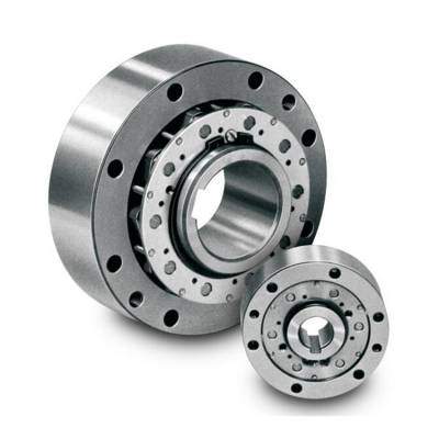
The utility model discloses a backstop with an overload protection function, which structurally comprises an outer ring, an inner ring and a wedge combination. The wedge combination is arranged in an outer ring inner circle between the inner ring and the outer ring, inner and outer contact ends, which are close to the inner ring and the outer ring, of each wedge are in arc-shaped design, and center points of the two arc-shaped contact ends of each wedge are non-coincident.
By means of changing the shapes of the wedges in the backstop, the backstop skids during overload, when the wedges are wedged, wedged angles are enlarged gradually along with increase of torque, and when the wedged angles are larger than friction angles, the wedges can skid on surfaces of the inner ring and the outer ring. When the torque is reduced, the wedged angles are smaller than the friction angles, and the backstop realizes normal backstop. When overload impact force is reduced, the backstop can normally operate again. Use safety of equipment is greatly increased.
Centers of the wedges are coincident to fixed centers thereof by means of calculation, so that the backstop is more stable in operation, and the service life of the backstop is prolonged.
In one word, the purpose of a backstop is to prevent undesirable reverse rotation. During operation, it permits rotation in only one specified direction of rotation.
The backstop functions by using centrifugal lift-off sprags. Once the lift-off speed is reached, the sprags lift off from the contact surface of the outer ring completely. It is lubricated with the gear unit oil.
Direction of Rotation
FLK Drive installs backstops according to the specifications given with the order. This means that it is necessary to specify the direction of rotation for the output shaft. The customer must check that the connected electric motor rotates in the correct direction. If not, the electric motor may damage the backstop.
The direction of rotation is determined with a view to the output shaft(LSS).
CW = Clockwise
CCW = Counterclockwise(anti-clockwise)